


Contents
Scroll to:
https://doi.org/10.37538/2224-9494-2023-1(36)-7-26
Scroll to:
Introduction. The historic cable-stayed suspension bridge of the city of Deir ez-Zor in Syria, which is an architectural monument, is described. The history of its creation at the beginning of the twentieth century and its destruction during the hostilities in 2013 is given. The importance of this bridge for the city and for the country as a whole is indicated, which was the reason for its choice as an object of research.
Aim. The study is intended to contribute to the restoration and (or) subsequent seismic strengthening of the cable-stayed suspension bridge of Deir ez-Zor.
Materials and methods. A detailed description and characteristics of the above-mentioned bridge, built according to the system of the French design engineer Albert Gisclard, according to the project of the design engineer Gaston Leinekugel Le Cocq and the construction company “Arnodin”, are given. Suspension and cable-stayed bridges are compared and distinctive features of Gisclard bridges are listed. Radial cablestayed trusses are described and the scheme of load distribution in suspension and cable-stayed bridges is illustrated. Examples of the calculation of the stay cables and their cross-sectional area are briefly given, which can be used in the restoration of the bridge and its cable stays. The method of protecting the bridge from wind and seismic influences is considered.
Results. Lines of influence for radial cable trusses of the Gisclard system are illustrated, showing tension and compression zones in the cable stays. Stiffening cables are recommended for adding to the design of multi-span cable-stayed and suspension bridges, as they increase their rigidity. To protect the cable-stayed suspension bridge of the city of Deir ez-Zor from wind and seismic vibration, a method of damping or reducing wind and seismic vibration using magnetorheological liquid dampers with tuned mass is proposed.
Conclusions. Conclusions are drawn about the feasibility of seismic strengthening of the Deir ez-Zor bridge together or after restoration with the help of the above-mentioned dampers, which allow protecting the bridge, while maintaining its authenticity and original exterior appearance.
Aldrebi Z.A. The first steps towards the restoration and seismic strengthening of the historic cable-stayed suspension bridge of Deir ez-Zor in Syria. Bulletin of Science and Research Center of Construction. 2023;36(1):7-26. https://doi.org/10.37538/2224-9494-2023-1(36)-7-26
The city of Deir ez-Zor is located in the northeast of the Syrian Arab Republic on the right bank of the Euphrates River, but part of it is located within the island in the middle of the river, where the river forks into two branches before entering the city, one large and the other small branch. The main attraction of this city was and is the so-called “suspension bridge of Deir ez-Zor” or “French bridge”. This bridge is a hybrid of a cable-stayed and suspension bridge built over the Euphrates River in six years (1925–1931) at a time when Syria was under the French mandate and connects the right and left banks of the above-mentioned river. Until 1980, it was used as a road bridge and a pedestrian bridge, but after that it was used exclusively as a pedestrian bridge in order to preserve it for future generations due toits architectural value to the country.
This pedestrian bridge is one of two bridges of the Gisklard system model built in Syria by the French Army, along with the Suvar Bridge on the Khabur River. The bridge was built according to the system of the French cable-stayed suspension bridge design engineer Albert Victor Hippolyte Leon Gisclard (Fig. 1a), the author of the bridge design was the French cable-stayed suspension bridge design engineer Gaston Leinekugel Le Cocq (Fig. 1b), who was the representative of the construction company “Arnodin”. This construction company belonged to Ferdinand Joseph Arnodin [11], who was also an engineer, industrialist and head of the above-mentioned construction company of the same name (Fig. 1c). Albert Gisklard died in 1909 in the south of France as a result of a catastrophe during load tests at the end of the construction of the railway cable-stayed suspension bridge “Pont de Cassagne”, which was later named after him “Pont Gisclard” [11–13].

Fig. 1. French design-engineers of cable-stayed suspension bridges of the late 19th century – the first half of the 20th century: a – Albert Victor Hippolyte Leon Gisclard (1844-1909); b – Gaston Leinekugel Le Cocq (1867–1965); c – Ferdinand Joseph Arnodin (1845–1924)
Рис. 1. Французские инженеры-проектировщики вантовых висячих мостов конца XIX – первой половины XX-го века: а – Альберт Виктор Ипполит Леон Жискляр (1844–1909); б – Гастон Лейнекугель Ле Кок (1867–1965); в – Фердинанд Жозеф Арнодин (1845–1924)
The cable-stayed suspension bridge of Deir ez-Zor (Fig. 2) consists of four main pylons and two side anchor pylons located on the right and left banks of the Euphrates River. The bridge consists of five spans, three main spans of 112.50 m each and two side spans of34.62 m each, i.e. (34.62 + 3 × 112.5 + 34.62). The total length of the spans of the bridge according to the project is 406.74 m. The width of the bridge, including sidewalks, is 3.5 meters, and excluding sidewalks is 2.7 m, the width of each of the two sidewalks is 40 cm. The total width of the bridge is 3.9 m. The weight of the bridge is approximately 390 tons. The stiffening girder is steel I-shaped form. The distinctive features of this bridge are the radial-stay trusses and the middle cable attachment node, which are the “hallmark” of the Gisklard system [11–13].
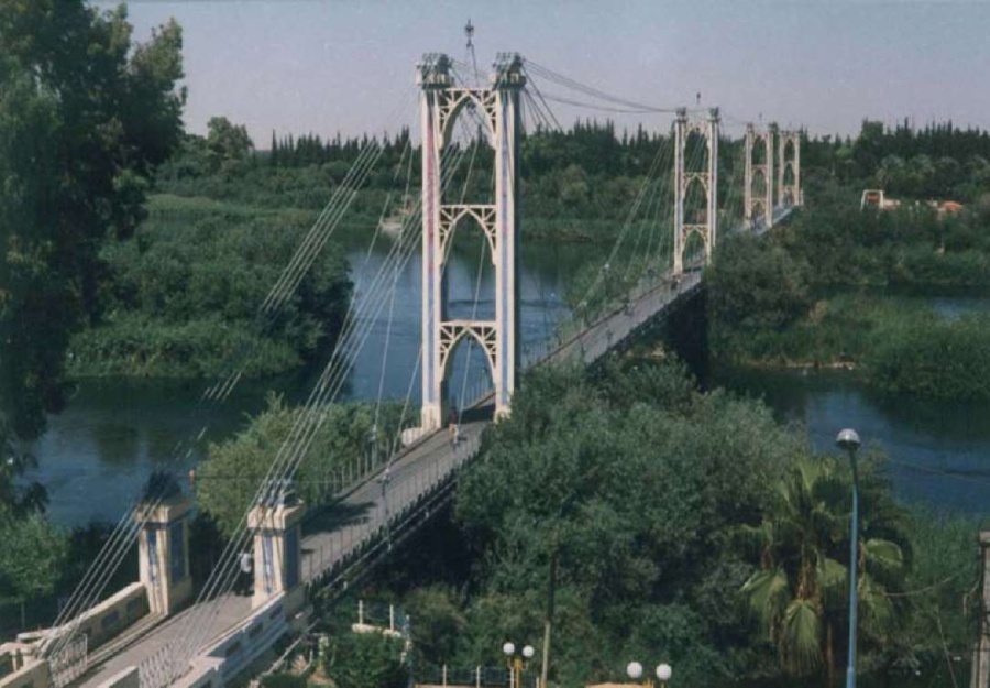
Fig. 2. The cable-stayed suspension bridge in Deir ez-Zor, Syria
Рис. 2. Вантовый висячий мост г. Дейр-эз-Зора, Сирия
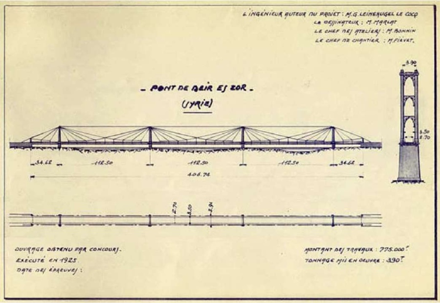
Fig. 3. The plan and section of the cable-stayed suspension bridge of Deir ez-Zor according to the Gisclard system. The author of the project is the French design engineer Gaston Leinekugel Le Cocq (1925) (photo from the archives of Arnodin – Leinekugel Le Cocq)
Рис. 3. План и разрез вантового висячего моста г. Дейр-эз-Зора по системе Жискляра. Автор проекта – французский инженер-проектировщик Гастон Лейнекугель Ле Кок (1925) (фото из архивов Арнодина – Лейнекугель Ле Кока)
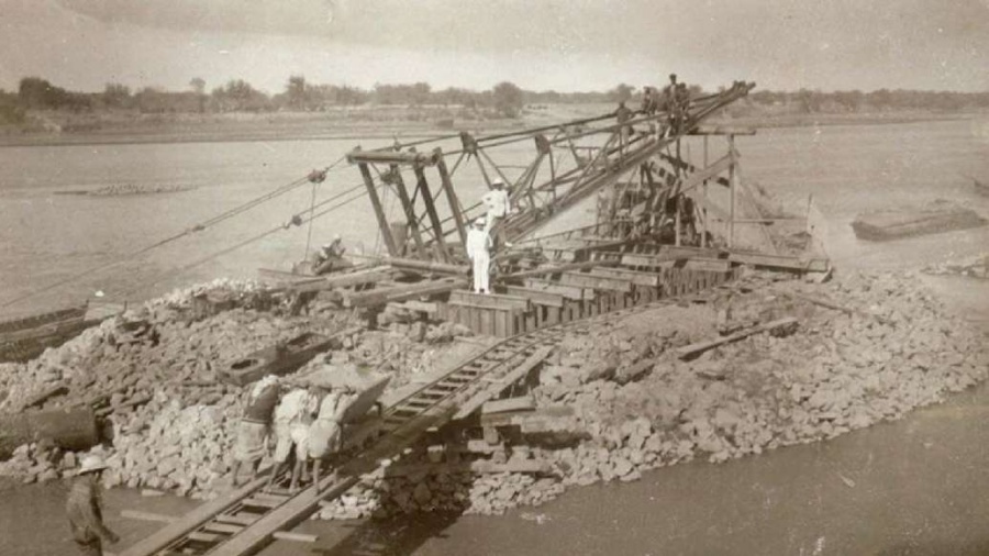
Fig. 4. The beginning of the construction of the cable-stayed suspension bridge in Deir ez-Zor, 1925. Installing a crane to erect a bridge pier (photo from the archives of Arnodin – Leinekugel Le Cocq)
Рис. 4. Начало строительства вантового висячего моста г. Дейр-эз-Зора, 1925 год. Установка крана для возведения опоры моста (фото из архивов Арнодина – Лейнекугель Ле Кока)
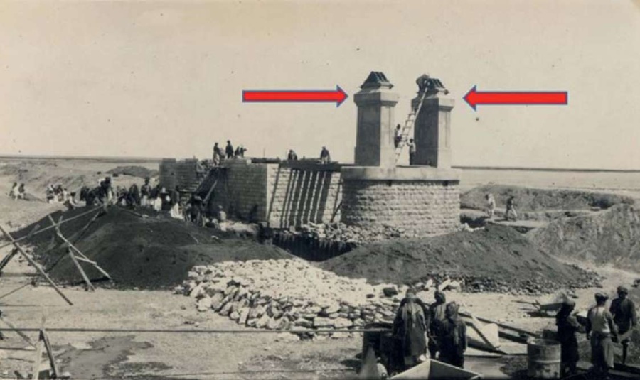
Fig. 5. The extreme anchor pylon of the cable-stayed suspension bridge in Deir ez-Zor in the process of construction in the 20s of the XX century (photo from the archives of Arnodin – Leinekugel Le Cocq)
Рис. 5. Крайний анкерный пилон вантового висячего моста г. Дейр-эз-Зора в процессе строительства в 20-е годы XX века (фото из архивов Арнодина – Лейнекугель Ле Кока)
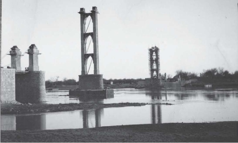
Fig. 6. The cable-stayed suspension bridge in Deir ez-Zor under construction, April 1928 (photo from the archives of the architect-archaeologist Maurice Pillet)
Рис. 6. Вантовый висячий мост г. Дейр-эз-Зора в процессе строительства, апрель 1928 года (фото из архивов архитектора-археолога Мориса Пилле)
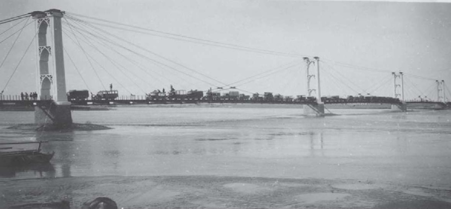
Fig. 7. Inauguration of the cable-stayed suspension bridge in Deir ez-Zor and testing the load bearing capacity of the bridge deck in 1931 (photo from the archives of Arnodin – Leinekugel Le Cocq)
Рис. 7. Открытие вантового висячего моста г. Дейр-эз-Зора и испытание несущей способности мостового настила в 1931 году (фото из архивов Арнодина – Лейнекугель Ле Кока)
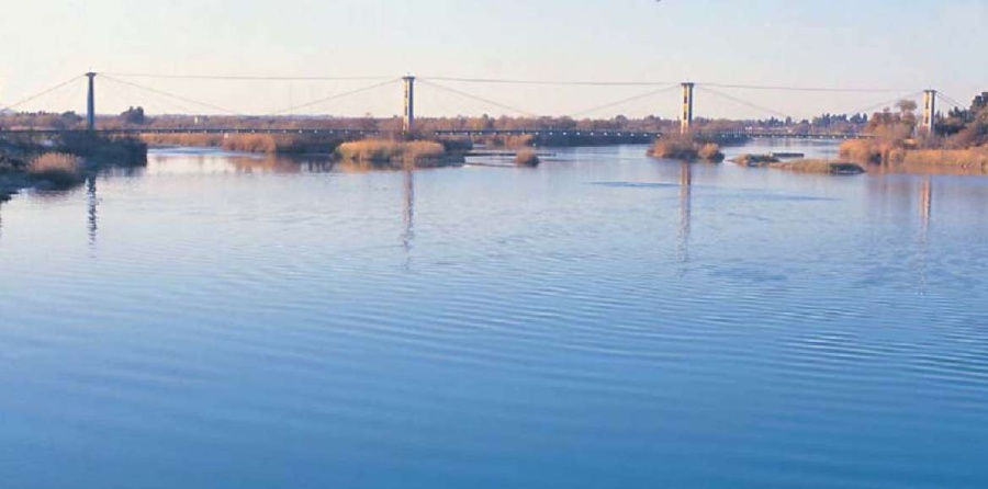
Fig. 8. General modern view of the Deir ez-Zor cable-stayed suspension bridge over the Euphrates River before destruction in 2013
Рис. 8. Общий современный вид вантового висячего моста г. Дейр-эз-Зора через реку Евфрат до разрушения в 2013 году
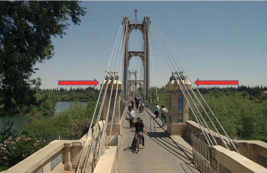
Fig. 9. The extreme anchor pylon of the cable-stayed suspension bridge in Deir ez-Zor (modern view until 2013)
Рис. 9. Крайний анкерный пилон вантового висячего моста г. Дейр-эз-Зора (современный вид до 2013 года)
The plan, section, and some stages of the construction of this bridge are shown in Figures 3–9, namely the beginning of construction in 1925, the construction process, load tests and the opening of the bridge in 1931, the modern view of the bridge in the XXI century, and photographs of the destroyed bridge after 2013 as a result of the war (Fig. 10–11).
During the hostilities in Syria, the bridge described above was damaged and destroyed (Fig. 10–11) in May 2013.
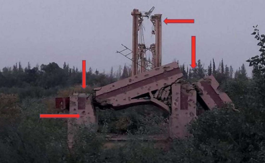
Fig. 10. Damaged and destroyed pylons of the cable-stayed suspension bridge in Deir ez-Zor. The arrows show damage
Рис. 10. Поврежденные и разрушенные пилоны вантового висячего моста г. Дейр-эз-Зора. Стрелками показаны повреждения
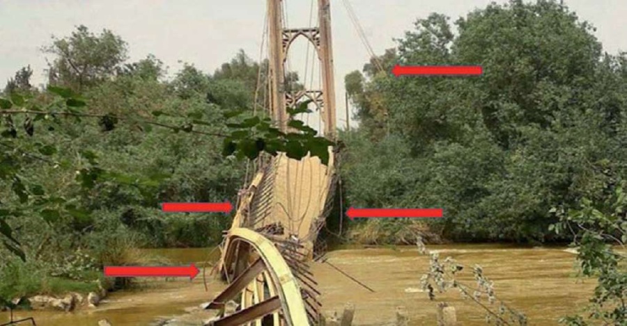
Fig. 11. The cable-stayed suspension bridge of Deir ez-Zor after destruction in 2013. The arrows show damage
Рис. 11. Вантовый висячий мост г. Дейр-эз-Зора после разрушения в 2013 году. Стрелками показаны повреждения
In the first half of the XX century, several bridges were designed and built by Gisklard's colleague Gaston Leinekugel Le Cocq, and Ferdinand Arnodin's construction company according to the Gisklard system. For example, a cable-stayed suspension bridge similar to the cable-stayed suspension bridge of Deir ez-Zor, but with an improved radial cable-stayed truss, the cable-stayed suspension bridge “Puente Colgante de Santa Fe” in the city of Santa Fe in Argentina (Fig. 12–13).
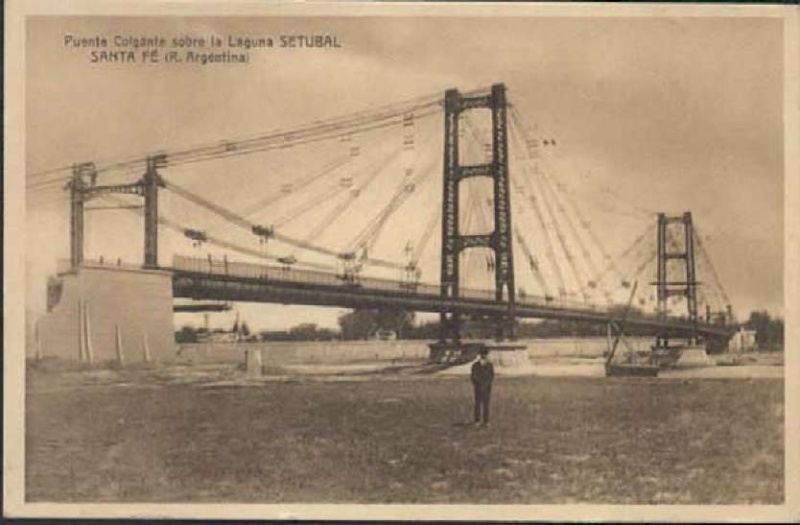
Fig. 12. “Puente Colgante de Santa Fe” bridge in Santa Fe, Argentina, with an improved radial cable-stayed truss of the Gisclard system (a circa 30s), (photo from the archives of Arnodin – Leinekugel Le Cocq)
Рис. 12. Мост «Puente Colgante de Santa Fe» в г. Санта-Фе, Аргентина, с улучшенной радиально-вантовой фермой системы Жискляра (примерно 30-е годы) (фото из архивов Арнодина – Лейнекугель Ле Кока)
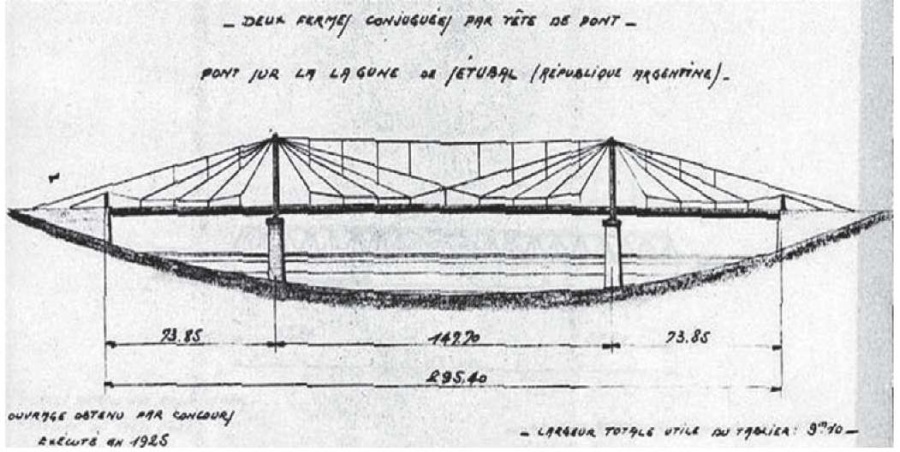
Fig. 13. The section of “Puente Colgante de Santa Fe” bridge in Santa Fe, Argentina, with an improved radial cable-stayed truss (approximately the middle of the 20s of the XX century) (photo from the archives of Arnodin – Leinekugel Le Cocq)
Рис. 13. Разрез моста «Puente Colgante de Santa Fe» в г. Санта-Фе, Аргентина, с улучшенной радиально-вантовой фермой (примерно середина 20-х годов XX века) (фото из архивов Арнодина – Лейнекугель Ле Кока)
In general, suspension and cable-stayed bridges have similar schemes, but they also differ in the way of supporting the stiffening girder called a deck on which the roadway is located. The main difference between suspension bridges and cable-stayed bridges is that in suspension bridges, the roadbed is supported by suspenders or, in other words, vertical cables attached to the main load-bearing cables stretched from above along the entire length of the bridge, and in cable-stayed bridges, the roadbed is supported by cable stays attached directly to the pylons.
In suspension bridges (Fig. 14), the stiffening girder is supported by a curvilinear thread (cable or chain), stretched through the tops of the pylons, the ends of which are fixed at the ends in the shore anchor supports of the bridge, and vertical suspenders [8–10].
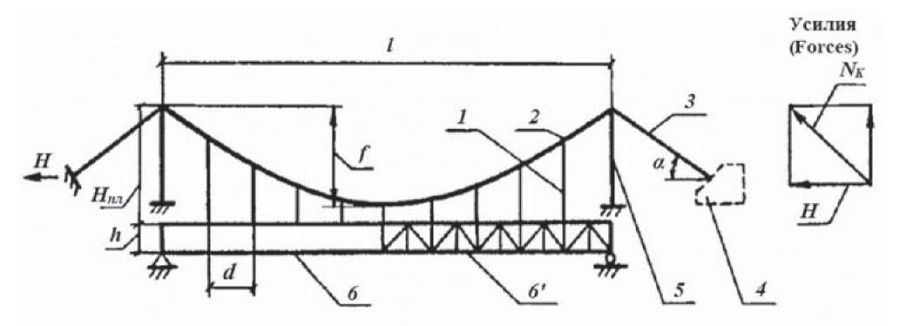
Fig. 14. Suspension bridge: 1 – vertical suspender; 2 – main suspension cable; 3 – anchor cable: 4 – anchorage; 5 – pylon: 6(6') – stiffening girder (truss); l – span of the bridge; Nk is the force in the anchor cable; H – thrust
Рис. 14. Висячий мост: 1 – подвеска; 2 – нить; 3 – оттяжка: 4 – анкерная опора; 5 – пилон; 6(6') – балка (ферма) жесткости; l – пролет моста; Nk – усилие в оттяжке (кабеле); Н – распор
In cable-stayed bridges (Fig. 15), the stiffening girder is supported by inclined rectilinear cables fixed on pylons [8][9][14–17][19]. These cables are called “cable stays”. They are fixed on the pylons in several ways (Fig. 16). The system is called radial if the cable stays are fixed at one point on the top of the pylon (fan system), and if they are fixed on the pylon at several points along its height and are parallel to each other, then this system of cable stays arrangement is called "harp".
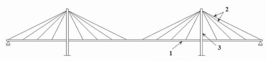
Fig. 15. A typical design scheme of a cable-stayed suspension bridge: 1 – stiffening girder; 2 – cable stays; 3 – pylon
Рис. 15. Типичная расчетная схема вантового моста: 1 – балка жесткости; 2 – ванты; 3 – пилон
Figures 14 and 15 illustrate the differences between typical suspension and cable-stayed bridges, respectively. Figures 14 and 17 clearly illustrate the differences between a typical suspension and a cable-stayed suspension bridge built according to the Gisclard system [6] with a radial-stayed truss (Fig. 17). The scheme of a bridge with a radial-stay truss, built according to the Gisklard system, is a prototype of modern cable-stayed bridges. This truss is a distinctive feature of the projects of the bridge design engineer Albert Gisklard along with the middle cable attachment node (Fig. 18).
The load distributions in suspension and cable-stayed bridges are somewhat different from each other. The load [17] distribution scheme for both types of bridges is shown in Figure 19.
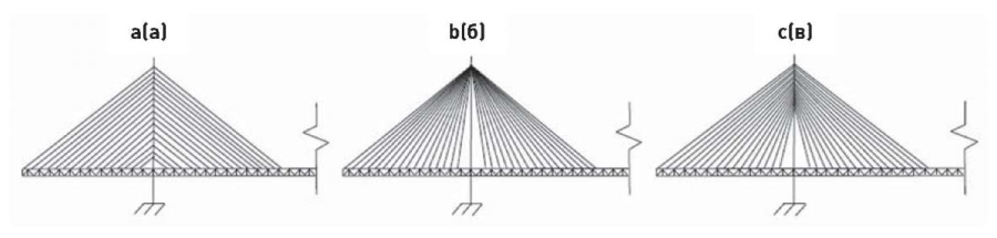
Fig. 16. Schemes of cable-stayed bridges: a – harp system; b – fan system; c – semi-harp system
Рис. 16. Схемы вантовых мостов: а – система «арфа»; б – система «пучок»; в – система «веер»

Fig. 17. Scheme of a cable-stayed suspension bridge of the Gisclard system: 1 – cable stay; 2 – pylon; 3 – anchor cable; 4 – vertical suspender; 5 – stiffening girder; 6 – anchorage; 7 – support; 8 – the supporting part of the stiffening girder
Рис. 17. Схема вантового висячего моста системы Жискляра: 1 – ванта; 2 – пилон; 3 – оттяжка; 4 – подвеска; 5 – балка жесткости; 6 – анкерное устройство; 7 – опора; 8 – опорная часть балки жесткости
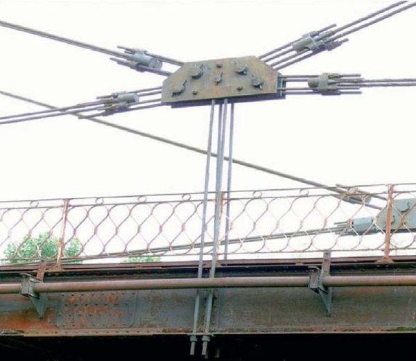
Fig. 18. Characteristic central node for the Gisclard system, element of the cable-stayed suspension bridge “Pont suspendu de Bourret” in France
Рис. 18. Характерный центральный узел для системы Жискляра, элемент вантового висячего моста «Pont suspendu de Bourret» во Франции
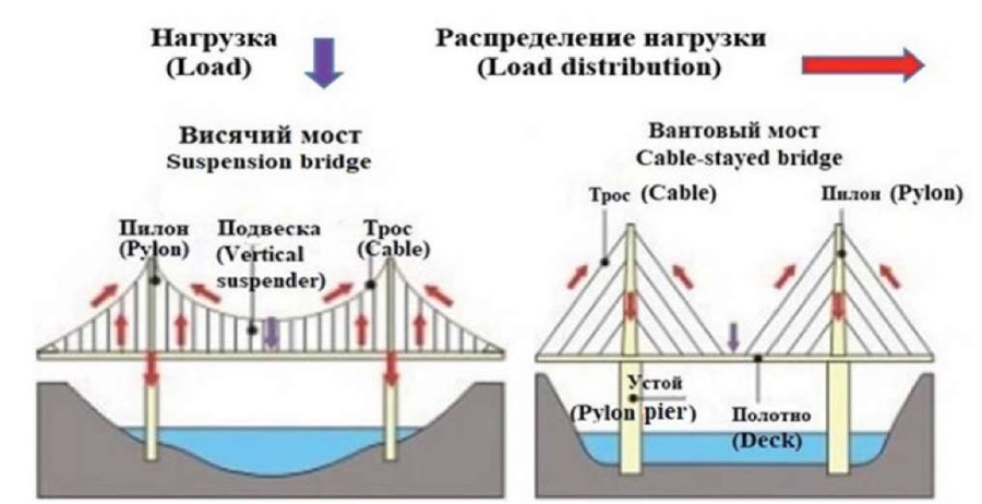
Fig. 19. Scheme of load distribution in suspension and cable-stayed bridges
Рис. 19. Схема распределения нагрузки в висячих и вантовых мостах
The following technique is designed to increase the rigidity of cable-stayed and suspension bridges by connecting the tops of the pylons with the help of an additional element in the form of a tightening of the so-called stiffening cable (Fig. 20–21). In addition, the use of a stiffening cable in the structures of the bridge superstructures reduces the consumption of material for the anchor supports of the bridges.
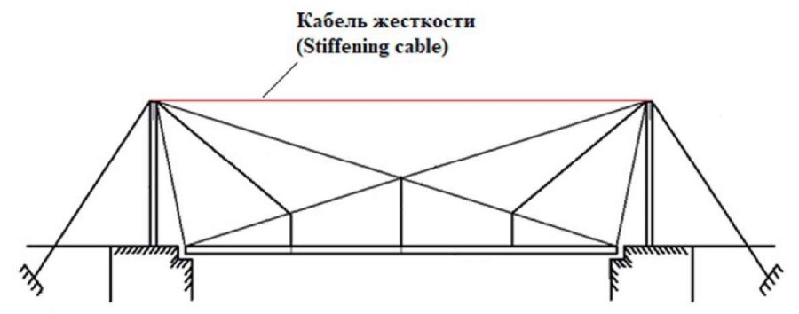
Fig. 20. Scheme of a cable-stayed suspension bridge of the Gisclard system, improved by the addition of stiffening cables by his colleague Gaston Leinekugel Le Cocq
Рис. 20. Схема вантового висячего моста системы Жискляра, улучшенная добавлением кабелей жесткости его коллегой Гастоном Лейнекугель Ле Коком
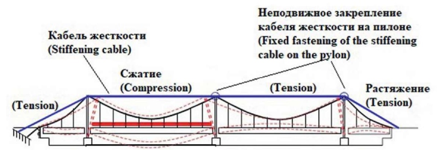
Fig. 21. Scheme of stiffening cable on suspension bridge pylons
Рис. 21. Схема кабеля жесткости на пилонах висячего моста
The cable must be able to resist large displacements; The cable needs to withstand the thrust caused by a temporary load; Temperature effects create additional stresses in the entire structure and in the cable and adversely affect its operation; When loading only one span, the cable works most efficiently. To increase rigidity, reduce cable sagging, and eliminate temperature deformations, that is, to increase the efficiency of its operation, immediately upon installation, it is pre-stretched by the amount of thrust arising from the temporary load. It should be noted that the cable in a loaded span works as a spacer, and in unloaded spans, it maintains its same tension without deforming. In a rectilinear cable, elastic deformations occur, which means that the deflections of the loaded span and the displacements of the pylon tops are small.
In the cable-stayed suspension bridge of the city of Deir ez-Zor, which was built according to the above-mentioned Gisklard system, its designer applied measures to increase rigidity, namely, stiffening cables were added (Fig. 22).
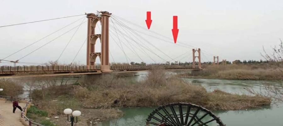
Fig. 22. Historic cable-stayed suspension bridge of Deir ez-Zor, Syria. The arrows show the stiffening cables
Рис. 22. Исторический вантовый висячий мост города Дейр-эз-Зора, Сирия. Стрелками показаны кабели жесткости
In the truss shown in Figure 23, each of the nodes, 1, 2, 3, 5, 6, 7, except for the middle node, that is, the “O” node is suspended only from the nearest pylon and is suspended from the adjacent truss node from the side of the second pylon. In the scheme under consideration, the influence lines are illustrated in Figure 23. Each cable stay is subject only to tensile forces, the condition for the cable stays to work in tension should be so that the top cable truss chords of one half-span (half-span are both sides of the “O” node) are located on a straight line with by the upper radial cable stay of the other half-span (Gisklard system). The disadvantage of this scheme is the high position of the “O” node, the large length of the vertical suspenders and high pylons.
To restore or strengthen the bridge (Fig. 24), it is necessary to make some calculations. For example, to calculate the stiffening girder [3][4], cable stays, anchor cables, pylons [6][10]. As an example, the algorithms for calculating the cable stays and their cross-sectional area are given below.
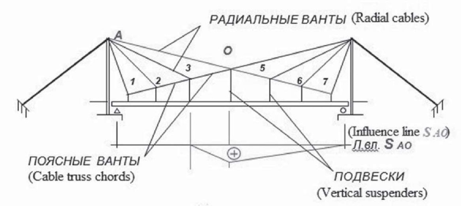
Fig. 23. Influence lines in a radial cable-stayed bridge truss of the Gisklard system
Рис. 23. Линии влияния в радиально-вантовой ферме моста системы Жискляра
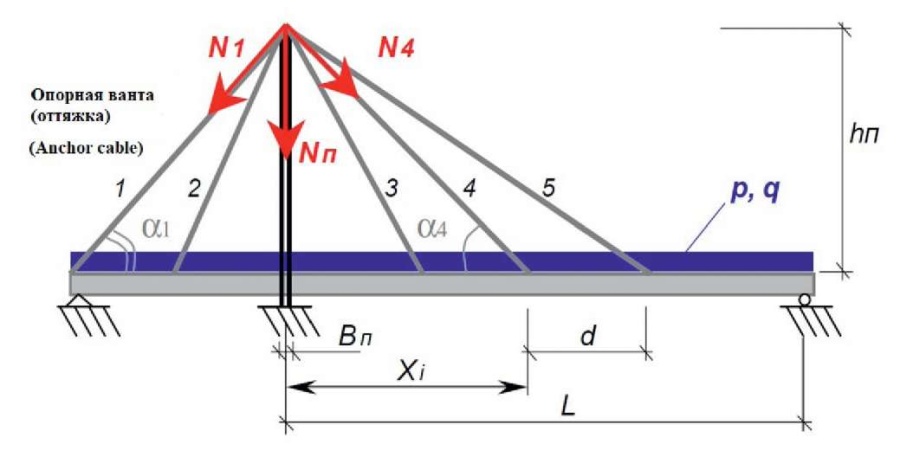
Fig. 24. Scheme for the calculation of the elements of a cable-stayed bridge
Рис. 24. Схема к расчету элементов вантового моста
When calculating the bridge, we use the following known values (Fig. 24): L – the size of the main span; d – panel, that is, the distance between the points of attachment of the cable stays on the stiffening girder; Xi – the distance from the pylon to the point of attachment of the cable stay on the stiffening girder; hп – the height of the pylon; Вп – the width of the pylon; p, q – the intensity of the permanent and temporary load, respectively; α1 – the angle No. 1 of inclination of the anchor cable (anchor cable stay) to the horizon;N1 – the force No. 1 in the anchor cable stay No. 1 (anchor cable No. 1); α4 – the angle No. 4 of inclination of the cable stay to the horizon; N4 – the force No. 4 in the cable stay No. 4; Nп – the force in the pylon.
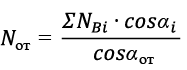
To determine the main forces NB in the cable stays, it is advisable to use the methodology proposed by professor V.K. Kachurin [6]:
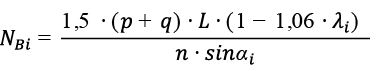 (1)
(1)
Or in general
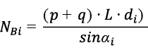 (2)
(2)
Where:
 – the distance from the pylon (to which the cable stay is attached) to the point of its attachment on the stiffening girder, expressed in fractions of the main span (Fig. 24).
n – the number of cable stays in the main span.
 (3)
(3)
It should be noted that the cross section for the longest cable stays is assigned greater than for the rest of the cable stays by at least 30 to 50 %.
According to the strength condition, can be obtained from the following expression:
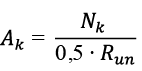 (4)
(4)
Where: Run – is the temporary tear resistance of the cable (brittle fracture), accepted for factory-made cables in the range of 1200–1800 MPa (1000–2400 MPa).
Since the territory of Syria is seismically hazardous with many earthquakes of varying intensity and frequency composition [1][2][14][18], which have occurred over the centuries, after the restoration of the cable-stayed suspension bridge of Deir ez-Zor, measures should be taken to protect it from wind [7] and seismic vibration [5][20] to ensure the safety of the bridge. Vibration reduction in cable-stayed suspension bridges can be achieved with tuned mass dampers, abbreviated (TMD), or with tuned mass magnetorheological dampers, abbreviated (TMD-MR DAMPER). Such damping systems have been studied by scholars W.J. Wu and S.C.S. Cai. The basic concept of cable vibration control with the TMD-MR damping system is shown in Figure 25, where the cable mass and the mass of the TMD-MR system are denoted m1 and m2 respectively. The MR damper provides adjustable damping and stiffness.
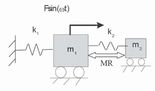
Fig. 25. Cable–TMD-MR system
Рис. 25. Система кабель–демпферы TMD-MR
A sketch of the proposed TMD-MR system that can be used for cable-stayed suspension bridges, including the cable-stayed suspension bridge of the city of Deir ez-Zor in Syria, is shown in Figure 26. It should be noted that when MR dampers are not used or removed, the TMD-MR damper system, actually turns into a conventional vibration damper, i.e. TMD without a damping element. Although the TMD usually has a damping element, the TMD component is hereinafter deliberately referred to as the case without a damping element to distinguish it from the TMD-MR damper, which consists of tuned mass dampers (TMD) and magnetorheological dampers (MR) components.
This TMD-MR damping system is designed to be installed on a cable, and the concept of vibration suppression is shown in Figure 26. Cable vibrations are caused by excitations from the interaction of the pylon, bridge deck, wind-rain-cable, or their combinations. Characteristics of cable vibrations can be obtained in the spectral diagram, which is processed according to accelerometer data (Fig. 26). Multiple peaks in the spectral diagram are assumed and should be expected, since cable vibration excitations can be single frequency, multi frequency, or random. The frequency of the TMD-MR system will be tuned to the frequency corresponding to the most significant resonant vibration i.e. highest peak (Fig. 27) or other target frequency along with adjustment of its location and damping ratio to dampen vibration as effectively as possible.
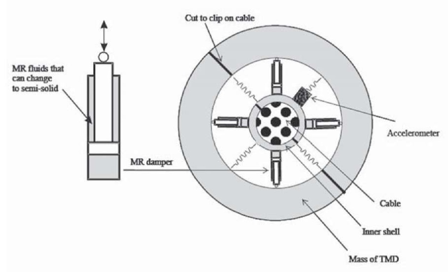
Fig. 26. Sketch of а TMD-MR damper system
Рис. 26. Эскиз демпферной системы TMD-MR
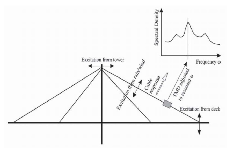
Fig. 27. Scheme of cable vibration control strategy
Рис. 27. Схема стратегии контроля вибрации кабеля
The cable-stayed suspension bridge of the city of Deir ez-Zor, which is an architectural monument and part of the history of Syria, deserves a better fate, so every effort must be made to restore it and subsequently strengthen this unique object with seismic. For this, some calculations were given as an example that can be used to restore the bridge deck, cable-stays, pylons, pylon piers or abutments.
To protect the cable-stays from vibration, it is necessary to take into account their vibrations caused by excitations from the interaction of the pylon, bridge deck, wind-rain-cable or their combinations. The cable-stays are susceptible to external disturbances due to their own low damping. Due to the peculiarities of their location, the effectiveness of vibration reduction by mechanical dampers cannot be fully exploited, therefore, it is proposed to use magnetorheological (MR) liquid dampers with tuned or adjustable mass (TMD), which combine the convenience of installing TMD and the adjustability of MR dampers. Such an MR-TMD damper can be mounted anywhere on the cable. Scholars in different parts of the world, such as W.J. Wu, S.C.S. Cai, G.E. Valdebenito, A.C. Aparicio and others have experimentally demonstrated the good effect of such a damper to reduce or suppress cable vibration during periodic excitation. The effectiveness of vibration reduction is affected by the ratio between the excitation frequency, the frequency of the cable and the frequency ofthe damper, taking into account this, the damper frequency is adjusted. This combination of dampers can also be used in power transmission lines.
Since it is important to preserve the original appearance and authenticity of the cable-stayed suspension bridge in the city of Deir ez-Zor in Syria, the use of the TMD-MR damper system is the most suitable to reduce vibration, of course, during or after the restoration of the bridge.
1. Aldrebi Z.A. Seismic hazard of the territory of Syria. Seismostoikoe stroitel'stvo. Bezopasnost' sooruzhenii = Earthquake Engineering. Constructions Safety. 2019;(6):43–48 (in Russian).
2. Ambraseys N.N., Jackson J.A. Faulting associated with historical and recent earthquakes in the Eastern Mediterranean. Geophysical Journal International. 1998;133(2):390–406. https://doi.org/10.1046/j.1365-246x.1998.00508.x
3. Bakhtin S.A. Determination of extreme values of internal forces in an arbitrary section of the stiffening girder of suspension bridges. In: Research in the work of artificial structures. Novosibirsk: Siberian Transport University; 1982, p. 36–42 (in Russian).
4. Belenya E.I., Streletsky N.N., Vedenikov G.S., Klepikov L.V., Morachevskii T.N. Metal structures. Special Course. Moscow: Transport Publ.; 1982 (in Russian).
5. Ettouney M., Hapij A., Gajer R. Frequency – Domain Analysis of Long – Span Bridges Subjected to Nonuniform Seismic Motions. Journal of Bridge Engineeringю 2001;6(6):577–586. https://doi.org/10.1061/(asce)1084-0702(2001)6:6(577)
6. Kachurin V.K., Bragin A.V., Erunov B.G. Design of suspension and cable-stayed bridges. Moscow: Transport Publ.; 1971. (in Russian).
7. Kazakevich M.I. Bridge aerodynamics. Moscow: Transport Publ.; 1987 (in Russian).
8. Kirsanov N.M. Calculation of suspension combined systems along the lines of influence, taking into account deflections. Voronezh: Publishing House of Voronezh University; 1976 (in Russian).
9. Kirsanov N.M. Suspension and cable-stayed structures. Moscow: Stroyizdat Publ.; 1981 (in Russian).
10. Kushnerev A.M. Design and calculation of suspension and cable-stayed bridges. Novosibirsk; 1969 (in Russian).
11. Leinekugel Le Cocq Didier. Ingénieur des ponts. L'histoire de l'entreprise Arnodin - Leinekugel Le Cocq de 1872 à 2002. Paris: La Vie du Rail; 2010 (in French).
12. Marrey B. Les ponts modernes 18e-19e siecle. Paris: Picard Éditeur; 1990 (in French).
13. Marrey B. Les ponts modernes 20 siecle. Paris: Picard Éditeur; 2000 (in French).
14. Omar H.M., Tatevosyan R.E., Rebetskiy Yu.L. The mechanisms of earthquakes and the stress state of the earth's crust in Syria. Vestnik KRAUNTs. Nauki o Zemle = Bulletin of Kamchatka Regional Association «Educational-Scientific Center». Earth Sciences. 2012;(20):139–148 (in Russian).
15. Perelmuter A.V. Fundamentals of calculation of cable-stayed systems. Moscow: Stroyizdat Publ.; 1969 (in Russian).
16. Petropavlovsky A.A., Kryltsov E.I., Bogdanov N.N., Iosilevskii L.I., Streletskii N.N., Potapkin A.A., Fridkin V.M., Kravtsov M.M. Cable-stayed bridges. Moscow: Transport Publ.; 1985 (in Russian).
17. Safronov V.S. Calculation of suspension and cable-stayed bridges for a moving load. Voronezh: Publishing House of Voronezh University; 1983 (in Russian).
18. Sbeinati M.R., Darawcheh R., Mouty M. The historical earthquakes of Syria: an analysis of large and moderate earthquakes from 1365 B.C. to 1900 A.D. Annals of Geophysics. 2005;48(3):347–435. https://doi.org/10.4401/ag-3206
19. Silnitsky Yu.M. Cable-stayed bridges. Leningrad; 1972 (in Russian).
20. Vader T., Mc Daniel C.C. Influence of Energy Dissipating Systems on the Seismic Response of Cable Supported Bridges. In: Proceedings of the 13th World Conference on Earthquake Engineering. Vancouver, Canada; 2004, paper No. 1046.
Ziad A. Aldrebi, Ph.D. in civil engineering, Researcher, Lecturer-researcher, Civil engineer
Moskovsky Ave., 9, Saint Petersburg, 190031, Russian Federation
tel.: +7 (911) 836-36-27
Aldrebi Z.A. The first steps towards the restoration and seismic strengthening of the historic cable-stayed suspension bridge of Deir ez-Zor in Syria. Bulletin of Science and Research Center of Construction. 2023;36(1):7-26. https://doi.org/10.37538/2224-9494-2023-1(36)-7-26

Краткие сведения об информационных партнерах РИА размещаются (по мере поступления) на сайте Академии.
109428, Moscow, 2-ya Institutskaya, 6
tel.: 89169595127
e-mail: Nat-7@yandex.ru


